1.0 Cooling Bed (66 Meter x 6 Meter) Straightening Grid Quantity : 1 set Arrangement : Directly below twin channel for receiving the bars Function : Cooling of the bars with simultaneous straightening effect Grid plates with serrated surface and provided with ventilation opening, cross transfer of the bars over the grid by means of moving rakes.
1.2 Fixed and moving rakes. Quantity : 1 set Function : Cooling of bars and cross transfers at the same time Length of each rake : 4000mm Notch pitch of rake : 80 mm Drive : DC Motor 70 KW
1.3 Aligning Device Quantity : 1 set Arrangement : In the stationary rake system of the cooling bed in front of the discharging device Function : Aligning the nose of the rolled bars in direction of forward transportation Type : Individually driven Numbers of driven rollers : 20 Number of non- driven Rollers: 15 Drive : 0.75 KW AC geared Motor
1.4 Bar Lift and Transfer system Type : Lift and Transfer system Qty : 1 set Total Length : 55 meters Lever spacing : 1 meter Lever operation : AC motor with gear- box
1.5 Run –out Roller Table Quantity : 1 Arrangement : Cooling bed discharge Roller table length : 66 Roller spacing : 1,200 mm Numbers of rollers : 37 Roller dia : 270 Roller length : 700 mm Drive : AC Motor group Drive
2.0 Bar Bundling Equipment 2.1 Chain Cross Transfer Type : Chain conveyor Quantity : 0ne (1) Conveyor width : Approx. 13.5 m Conveyor length : Approx. 5 m Conveyor speed : Approx. 7 m/min Consisting of : Tilting device at the roller table For lifting the bars and transfer
2.2 Stopper And Chute Type : Single rotating shaft Quant1ty : One (1) Drive : AC motor through worm gear box And brake
2.3 Trough Type Conveyor Type : Individual drive type by geared motor Quantity : One (1) Table length : Approx. 28m Table speed : Approx. 2m/s Roller pitch : 1000mm Including : Bundle former Disappearing stop Load cell for weighing
2.4 Chain Transfer Type : Chain conveyor Quantity : One (1) Conveyor width : Approx. 14 m Conveyor length : Approx. 3 m Conveyor speed : Approx. 15m/min
QST / TMT Equipment
Quenching and self tempering system also known as Thermo mechanical treatment Consist of a steel fabricated quenching box where Hot bar during rolling is subjected to rapid Cooling by a series of cooling elements Located with in. Water from a circulation system is pumped to these cooling nozzles through control valves. With in the box, bar surface is rapidly cooled with core of the bar remaining hot. Once the bar exit out of quenching box, heat from the core will reach the outer surface to give a tempering effect.
SPECIFICATIONS Range : Dia 8mm to Dia 32mm Lines : 3 nos Length : 10 meters Water flow : 220 cubic meters / hour
NSTRUMENTATION All process parameters are precisely controlled to achieve the right mechanical properties of the finished QST bar through a dedicated instrumentation system. System consists of two radiation pyrometers to monitor the bar temperature before & after the quenching process, Transmitters to monitor the water flow, pressure, temperature. All process parameters are displayed on operator computer monitor. Water flow to the system is controlled by a motorized control valve on the main header.
BY PASS LINE A by pass line is provided on the quenching box frame to convey the non quenched bar to cooling bed when the QST process is not in operation.
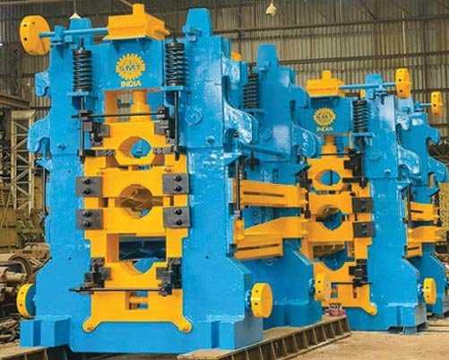
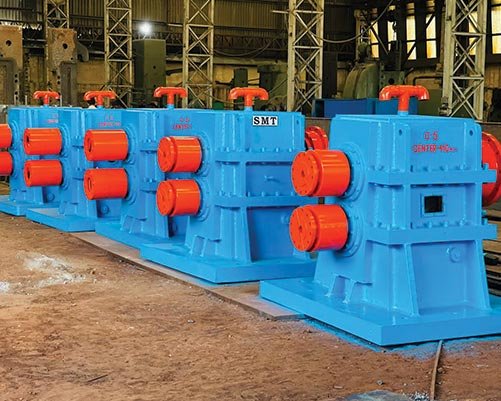
Continuous Shear For Bar Dividing Application
Continuous shear designed for dividing the finished QST / TMT bars to the desired length for further handling at cooling bed.
Shear is built on a gear box with body fabricated out of steel plates and with hardened and ground gears running on antifriction bearings. Gears and bearings are forced oil lubricated by a dedicated oil lubrication system. Blades are made of Die steel and heat treated for right hardness.
A pneumatic operated bar shifter will divert the cut bar to two finished bar line on the cooling bed.
SPECIFICATIONS Shear centers : 500 mm Capacity : To cut dia 8mm to dia 12mm QST / TMT bars Shear speed : 19 meters per second Motor capacity : AC Motor 45KW Controls : Digital AC motor controller with programmable logic controller for total shear control
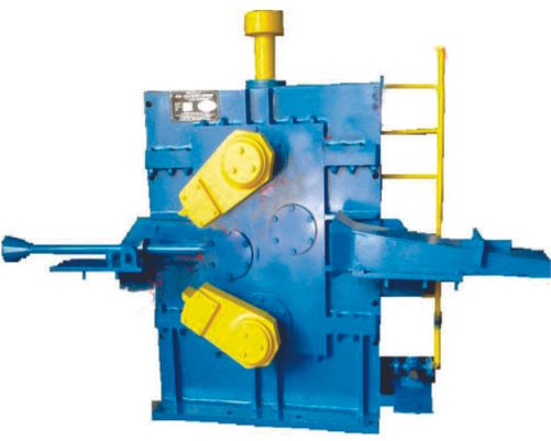
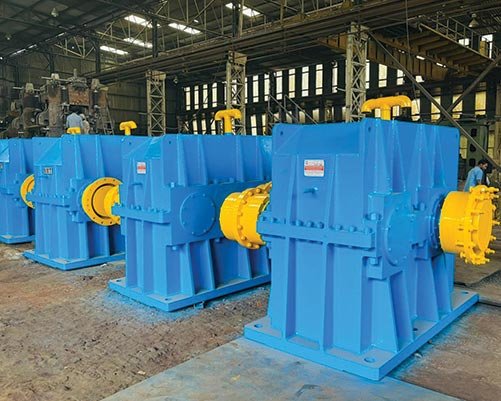
Flying Shear For Bar Dividing Application
Flying shear designed for dividing the finished QST / TMT bars to then desired length for further handling at cooling bed. Shear is of direct driven, start – stop type.
Shear is built on a gear box with body fabricated out of steel plates and with hardened and ground gears running on antifriction bearings. Gears and bearings are forced oil lubricated by a dedicated oil lubrication system. Blades are made of Die steel and heat treated for right hardness. A pneumatic operated bar shifter will divert the cut bar to two finished bar line on the cooling bed.
SPECIFICATIONS Shear centers : 1000 mm Capacity : To cut dia 8mm to dia 25mm QST / TMT bars Shear speed : 4 to 17 meters per second Motor capacity : DC Motor 135KW Controls : Digital DC motor controller with programmable logic controller for total shear control
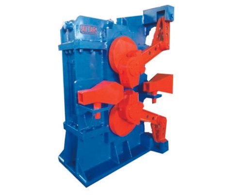
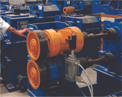
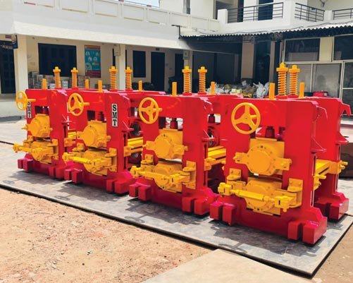
Pneumatic Operated Pinch Roll/tail Braking Pinch Roll
Pinch roll unit is a part of the QST system built to guide the rolled bar from finishing stand through the water quenching unit. Pinch roll unit is also used as a braking unit to retard the cut bar during rolling at high speeds
Equipment consists of a set of rolls made of wear resistant casting, mounted on shafts supported on antifriction bearings. Top and bottom roll bearing housings are located on fabricated links pivoted on pivot frame. Top roll link is connected to a pneumatic cylinder which will control the pinching pressure of rolls on the bar.
Drive to the rolls from Motor is transmitted through a pinion gear box with hardened and ground gears. Gears and bearings of the gear box are splash oil lubricated. Pinch roll unit, gear box and motors are mounted on a common base frame.
SPECIFICATIONS Roll Diameter : 300mm max, 270mm min Roll width : 70mm Speed : 4 to 17 meters per second Motor : 22Kw, 1440 RPM